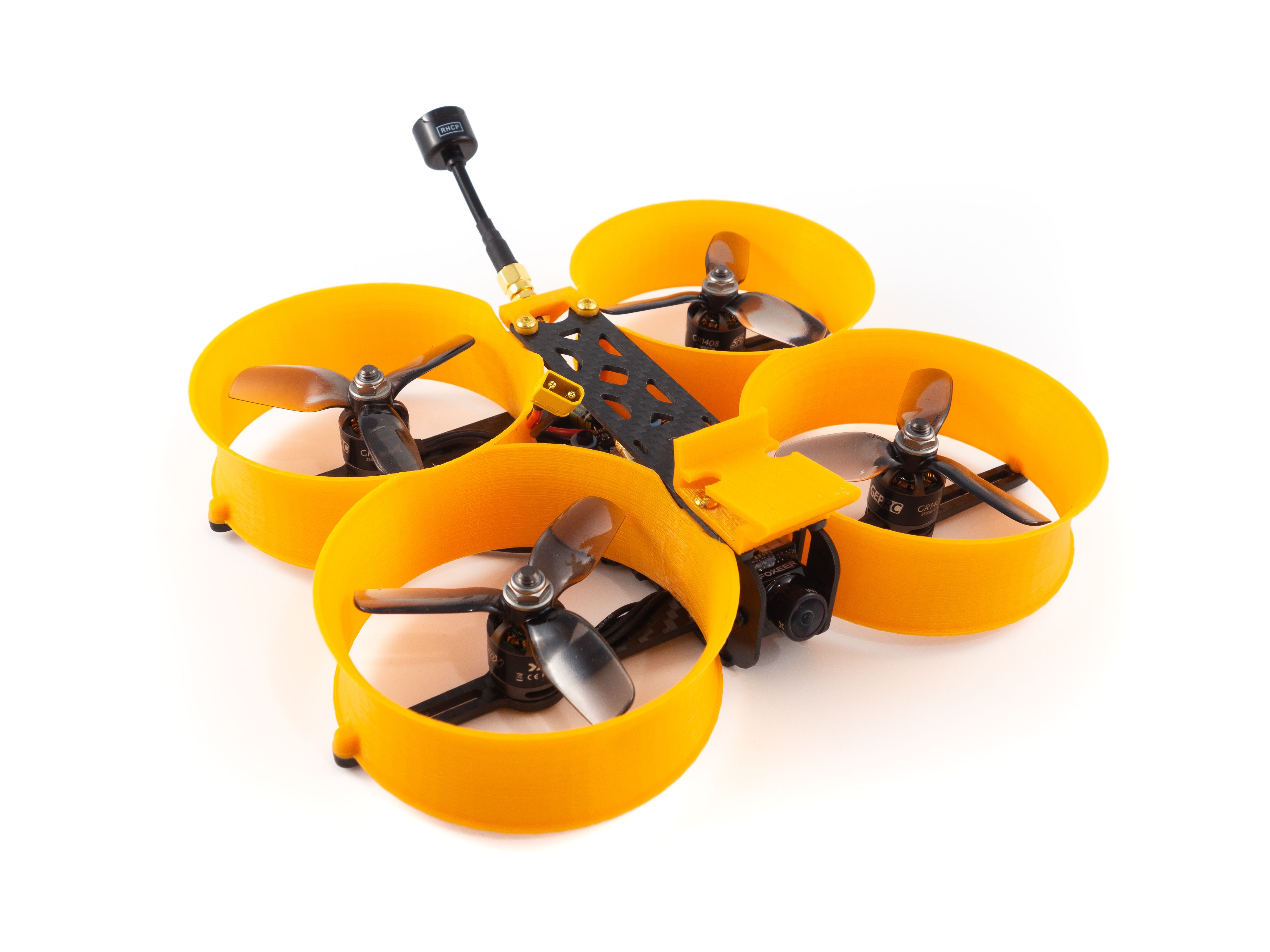
Apie šį buildą
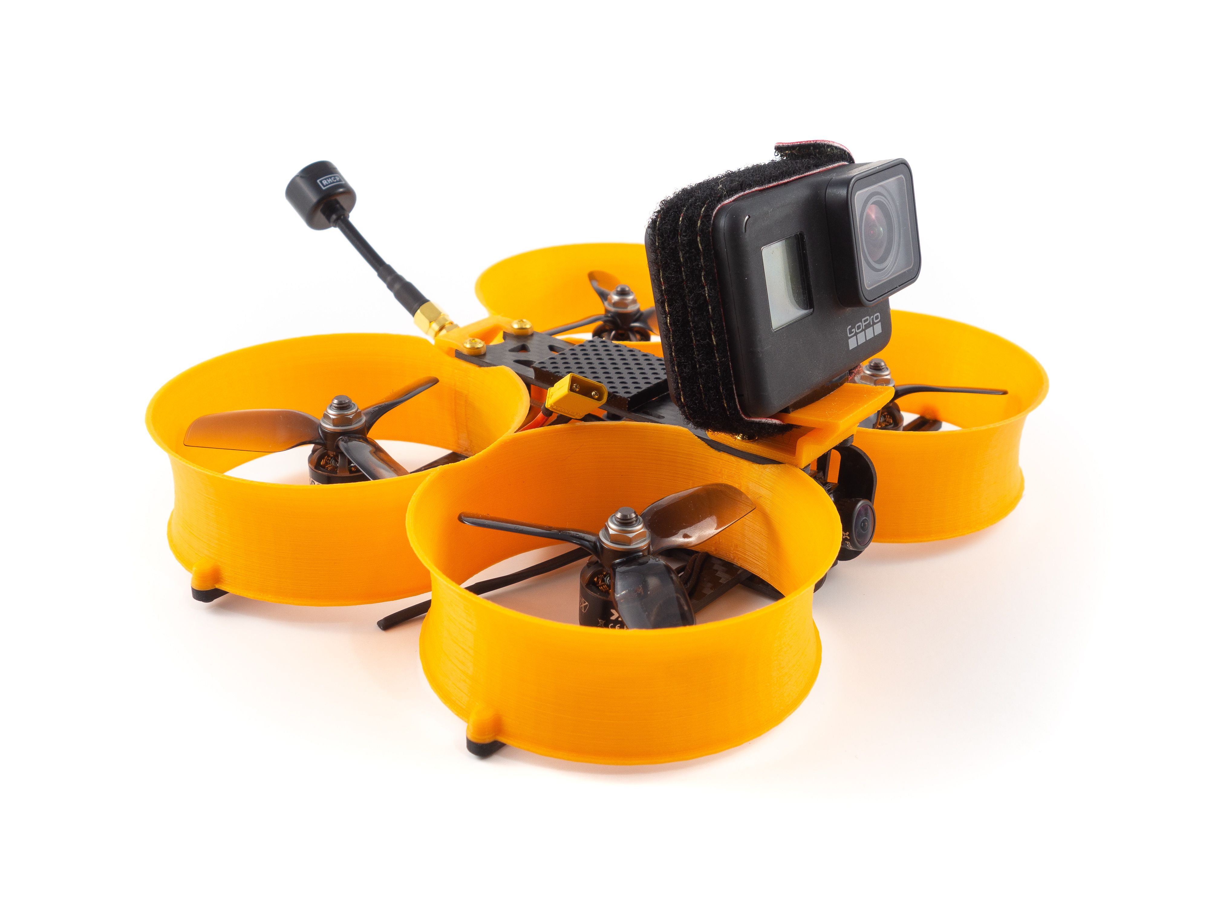
You've probably heard the term "Cinewhoop". Traditionally it's a 3" ducted quad capable of carrying a GoPro Hero7 Black at a low 10 degree angle. More recently the term "Cine" has been applied to a number of RTF quads ranging from 85mm to 3". They all focus on their HD capability, but none compare to the stabilization of Hypersmooth (only available on the Hero7 Black). This is what really offers that cinematic style footage. Now there's also ReelSteady Go which applies a similar stabilization algorithm to previous GoPro models, but Hypersmooth is what popularized this style of build.
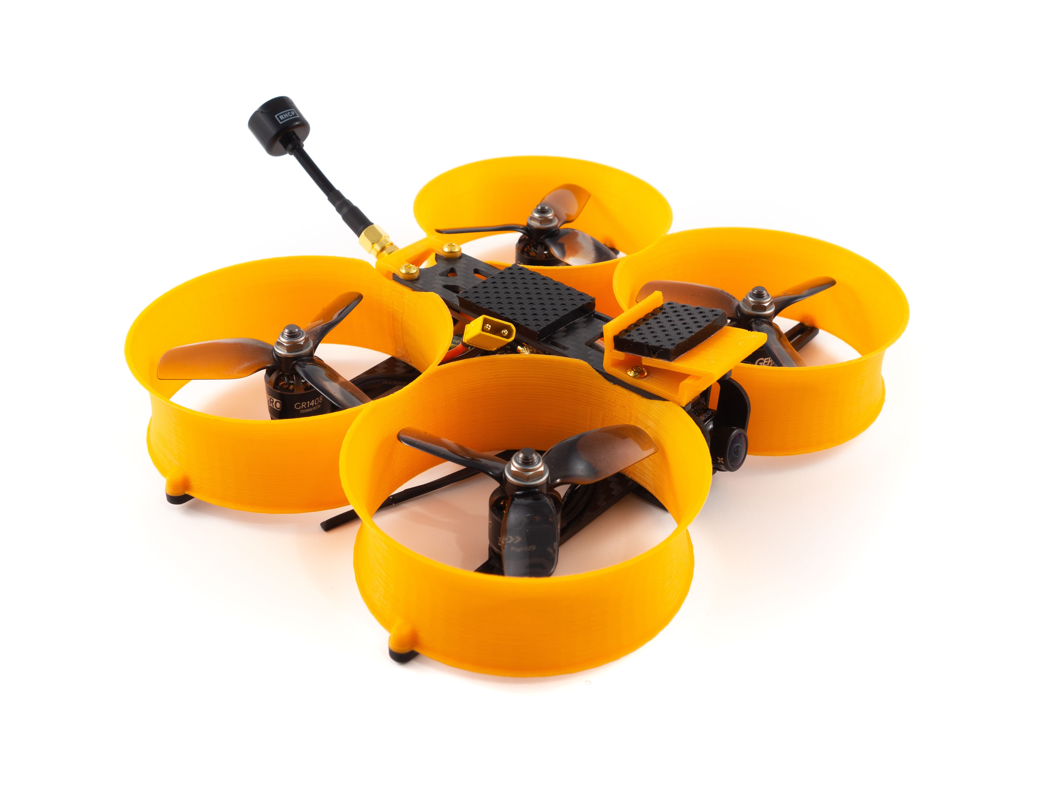
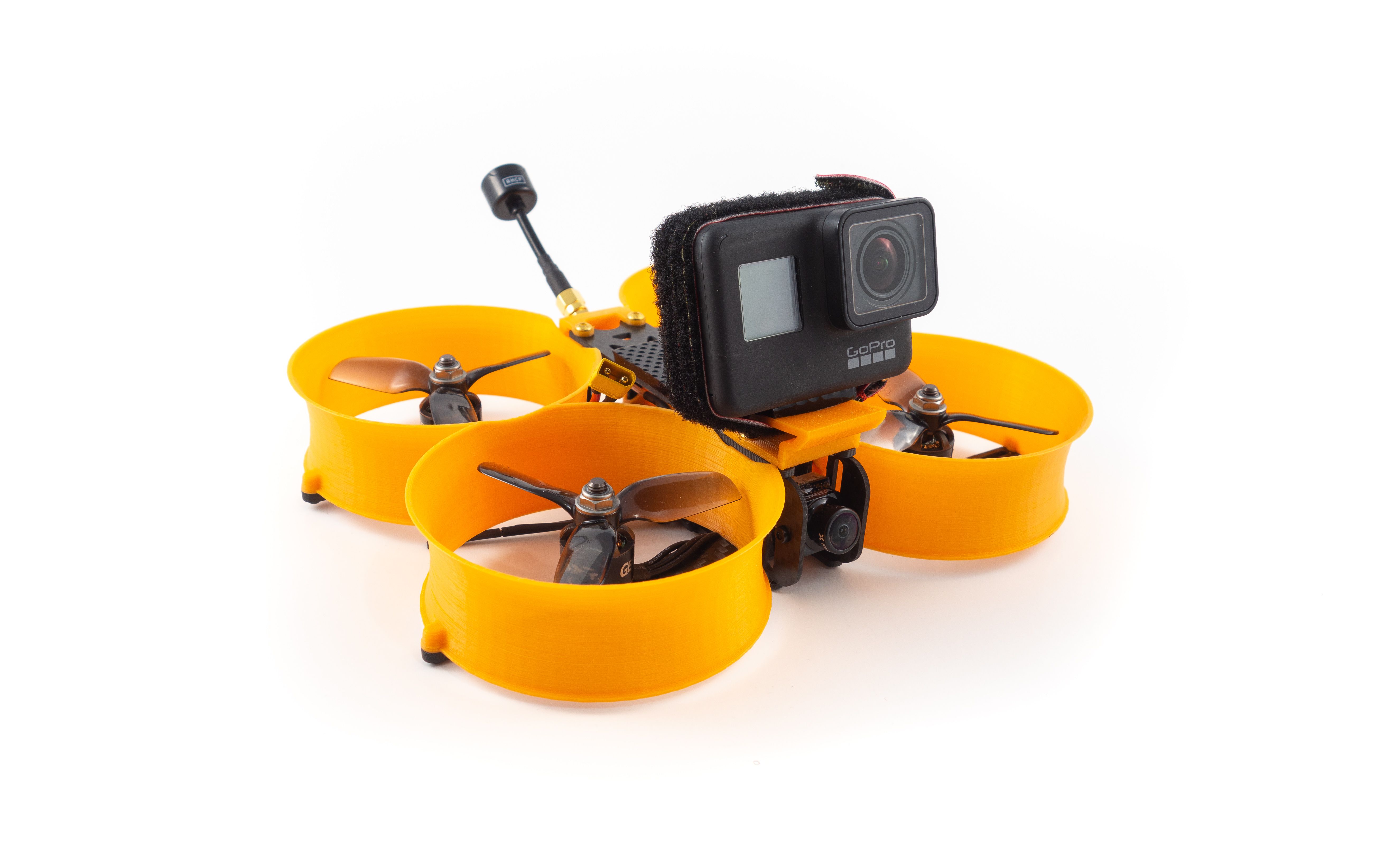
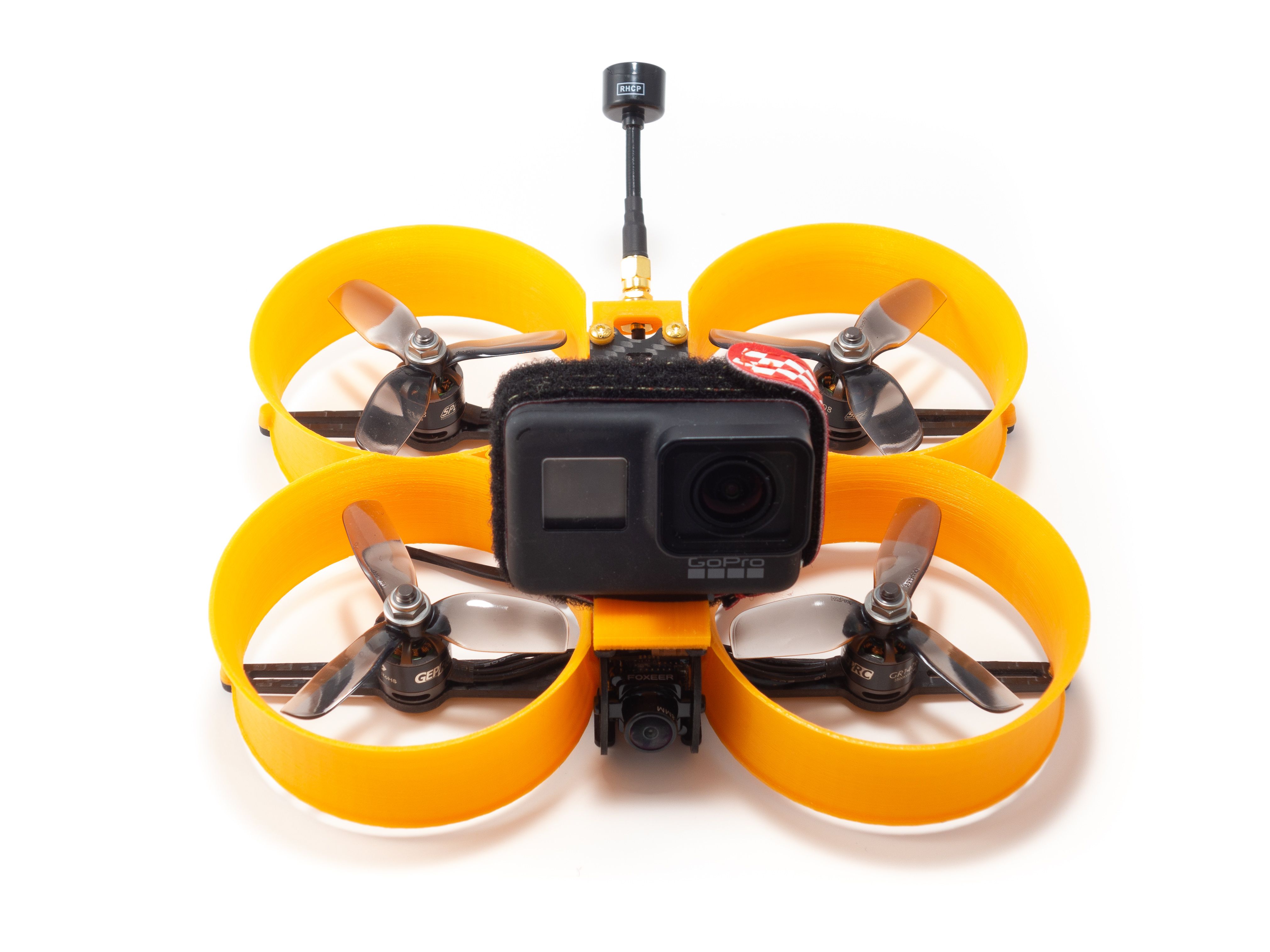
Now a traditional Cinewhoop isn't cheap. The most popular frame, the Squirt 2 commands a high price. This build is my attempt to build a Cinewhoop at a budget price, yet still offer the same cinematic style footage. It weighs in at 217g dry and 443g AUW with an 850mah 4S battery with a GoPro Hero7. I'm running the 3500kv motors.
ToolsThis is a moderately challenging build and does require a lot of fine soldering. With the proper tools and a lot of patience you can pull through. I highly recommend a flux pen, good 63/37 leaded solder and a quality soldering iron. Here are the tools and supplies you'll need. I've included direct links to my gear below.
- Soldering iron
- 1.5mm and 2.0mm hex drivers
- Industrial Tweezers
- Wire cutter/stripper
- Scissors
- Heat gun or lighter
- Ruler and cutting mat
- Multimeter
- A variety of heat shrink tube sizes
- Blue Loctite
- Zip ties (small)
- 63/37 leaded solder
- Liquid soldering flux pen
The frame kit comes with everything you need except for enough 6mm M2 screws to mount your stack. In fact, it's only one screw short. The stack doesn't come with hardware so I recommend buying an M2 screw kit. I linked my kit below. Other than that you don't need to purchase any additional hardware.
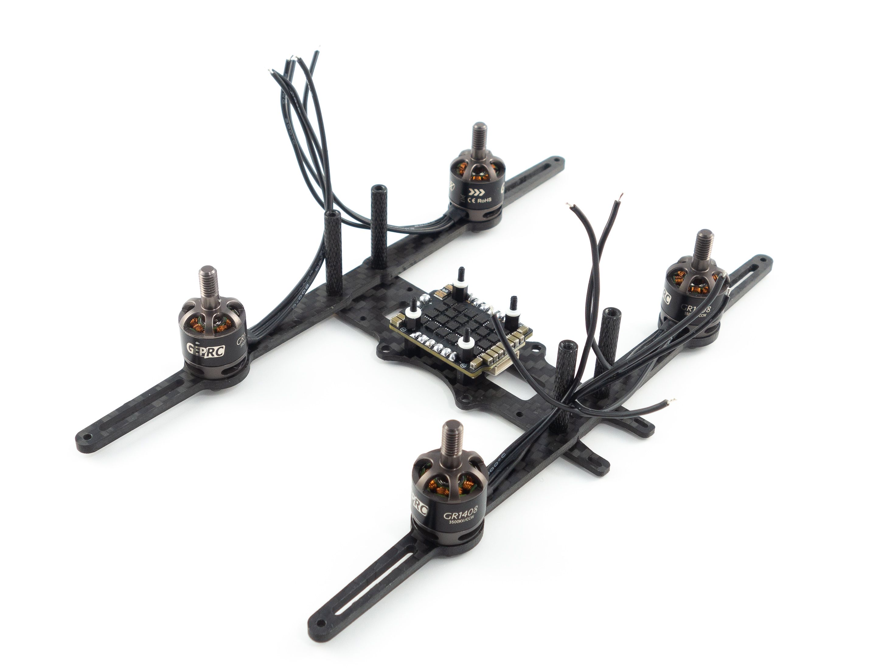
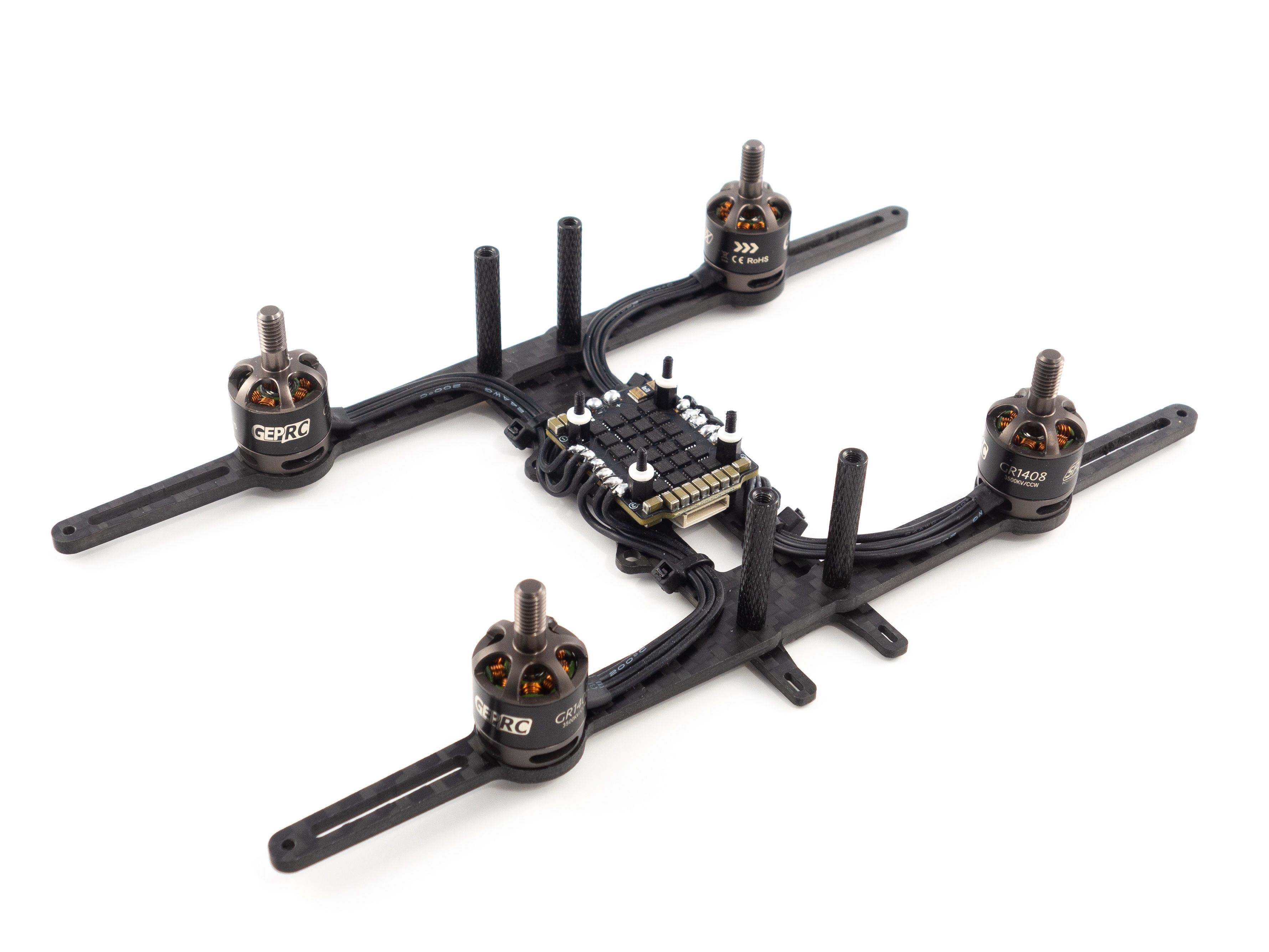
Frame AssemblyThis frame is really easy to assemble. You don't need the ducts or any of the TPU parts just yet, so save those for the end. To start you only need the base plate and the arms. Use the included gold screws to mount the arms on top of the base plate. Screw the black standoffs above to hold everything in place.
Motors
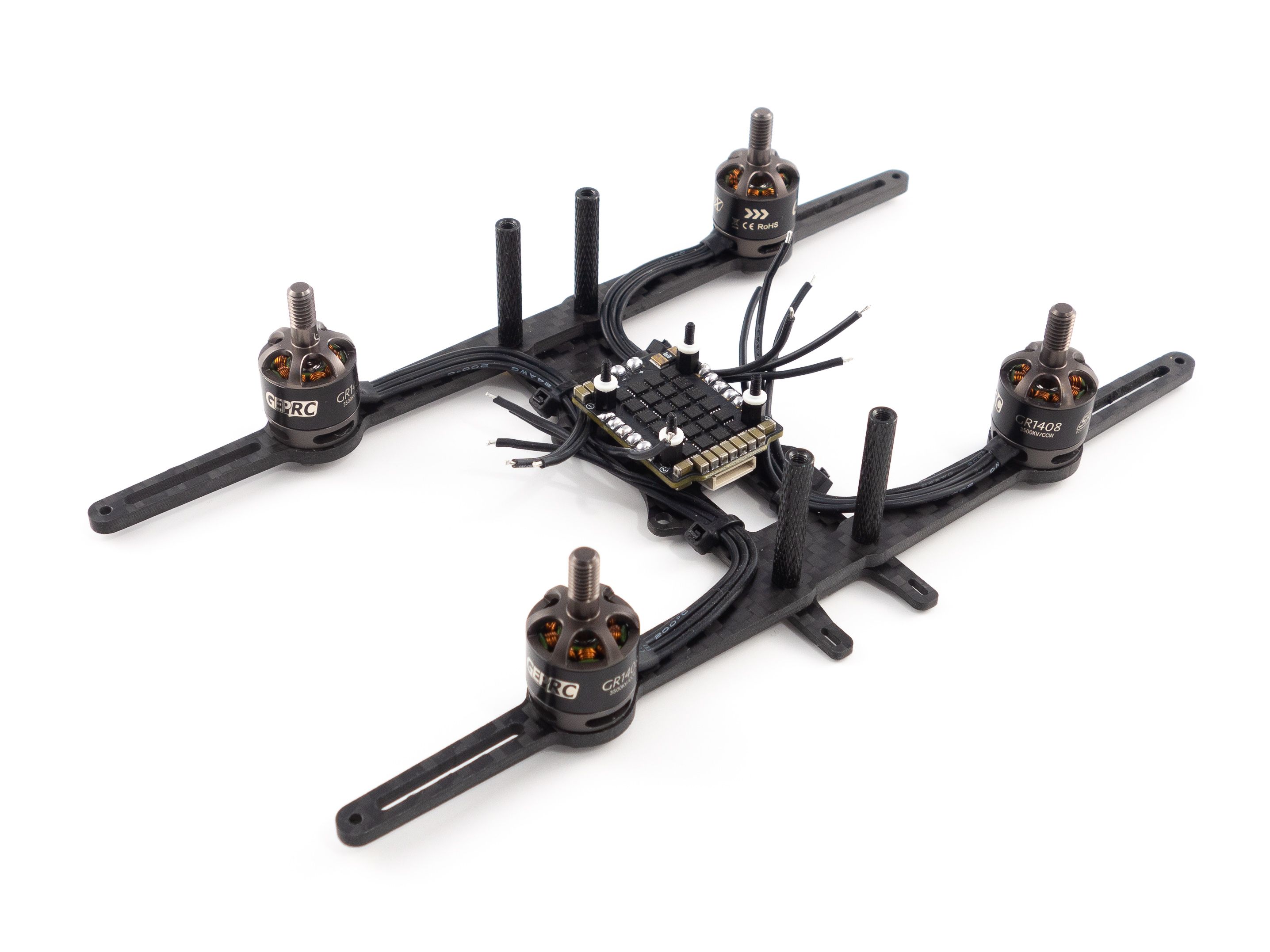
Now this is where things start to get a little tricky. Mount the motors onto the arms using the included screws. It's helpful to use blue Loctite to ensure the screws don't vibrate out. Once you've done that it's prudent to do a little wire management. I used zip ties to direct the wires across the bottom plate. You want the wires to follow the arms, but not all the way to the standoffs. They need to drop down off to the side so the ducts don't pinch them later. The zip ties help hold them in place so you can solder them to the ESCs.
Once you're ready to solder you need to remove the flight controller from the stack. Do this by unscrewing the nylon nuts on top and unplug the FC from the 4-in-1 ESC. Now you can mount the 4-in-1 ESC to the frame using the aforementioned M2 screws. Make sure the battery tabs point toward the rear of the frame. The front has the camera mount tabs.
Before soldering it's a good idea to flux all the motor tabs then apply a ball of solder to each tab. The pads are really close together, so you may accidentally bridge them. To fix that just apply some flux and slice through the middle with your iron. Now if you're right-handed start with the rightmost pad and solder your motor wires to the pads one at a time. Cut each to length as you go and be sure to give yourself a little slack. Again, if you accidentally bridge the pads just apply some flux and be patient. This can be a tedious process.
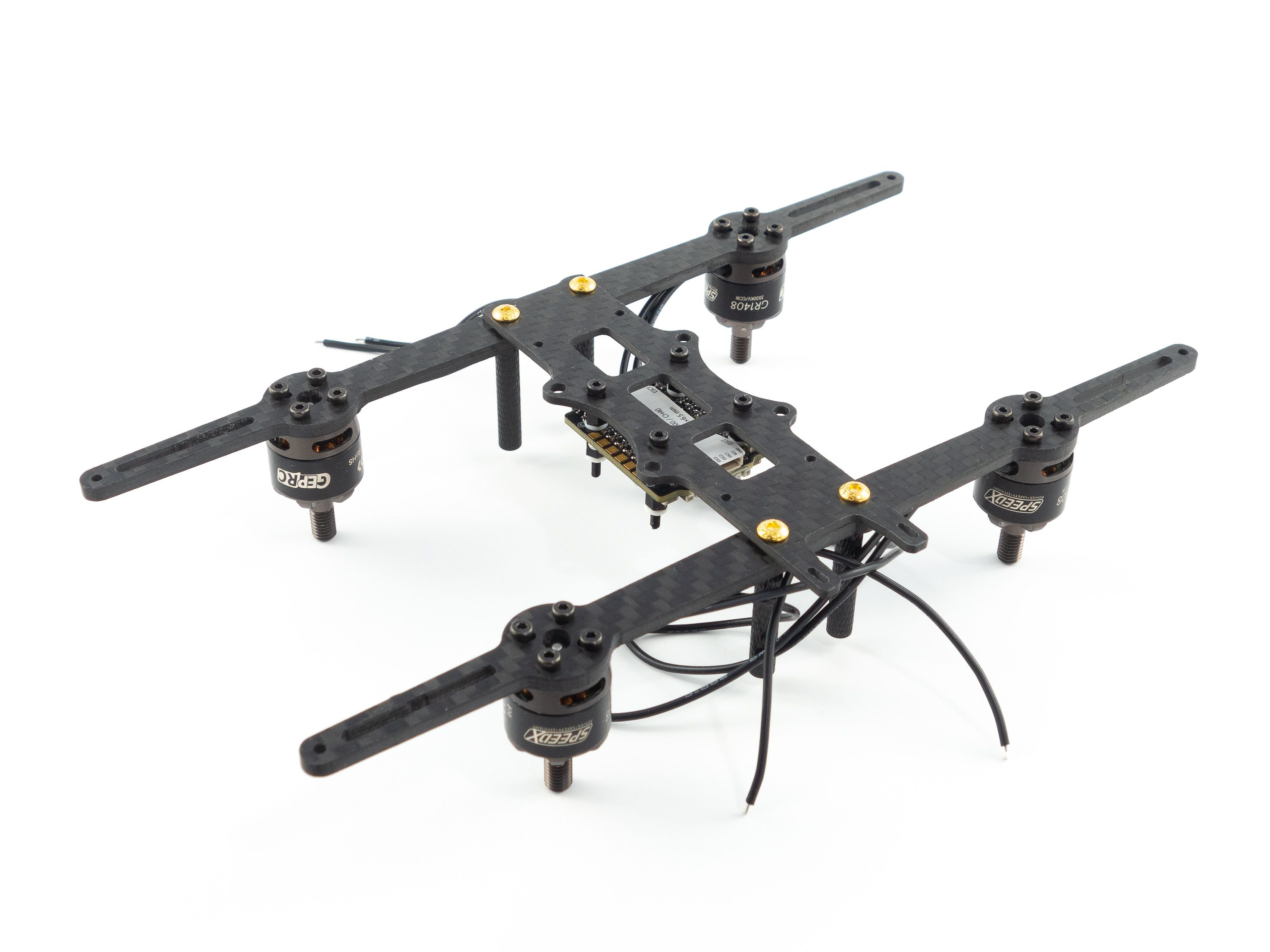
Power Connector
Congratulations! You've just completed the most difficult part of the build. Now you can solder the power leads. Everything you need is at the bottom of the Mamba container.
- Solder the wires to the XT30 connector first and make sure you've got the polarity correct. Add shrink tube to cover the joints.
- We want the battery lead to come up to the side of the battery between the ducts, so measure the wire and cut it to length. Keep in mind that one wire should be cut a little shorter than the other to allow the wires to run to the side.
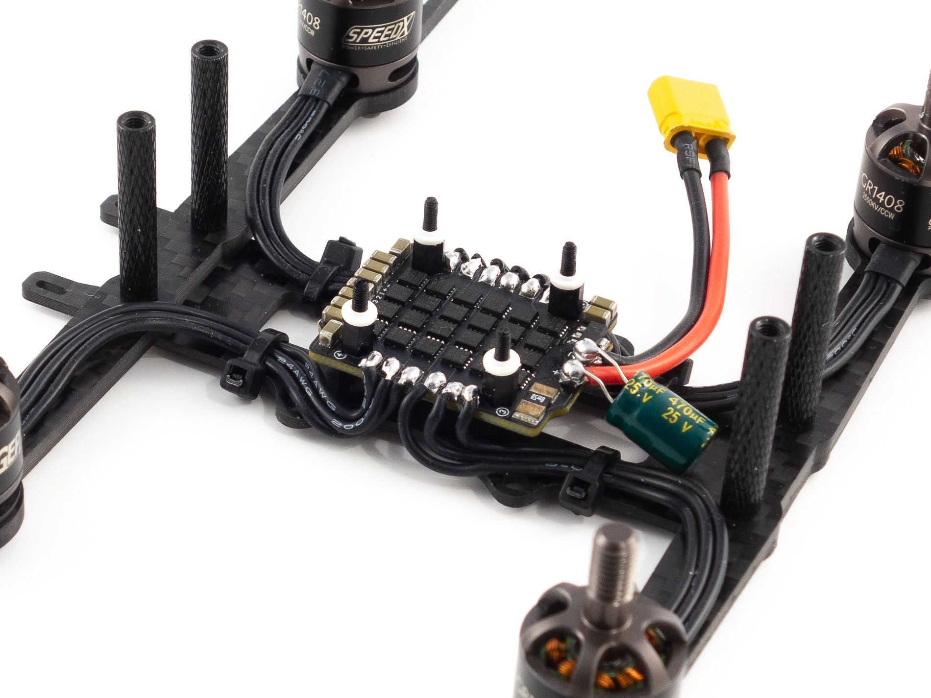
- Flux and add solder to the battery pads on the 4-in-1 ESC and solder the wires to the pads.
- Use a steady hand and be very careful not to accidentally bump the components on the board with your iron.
- Solder the capacitor on top of the battery leads.
- The striped side is negative.
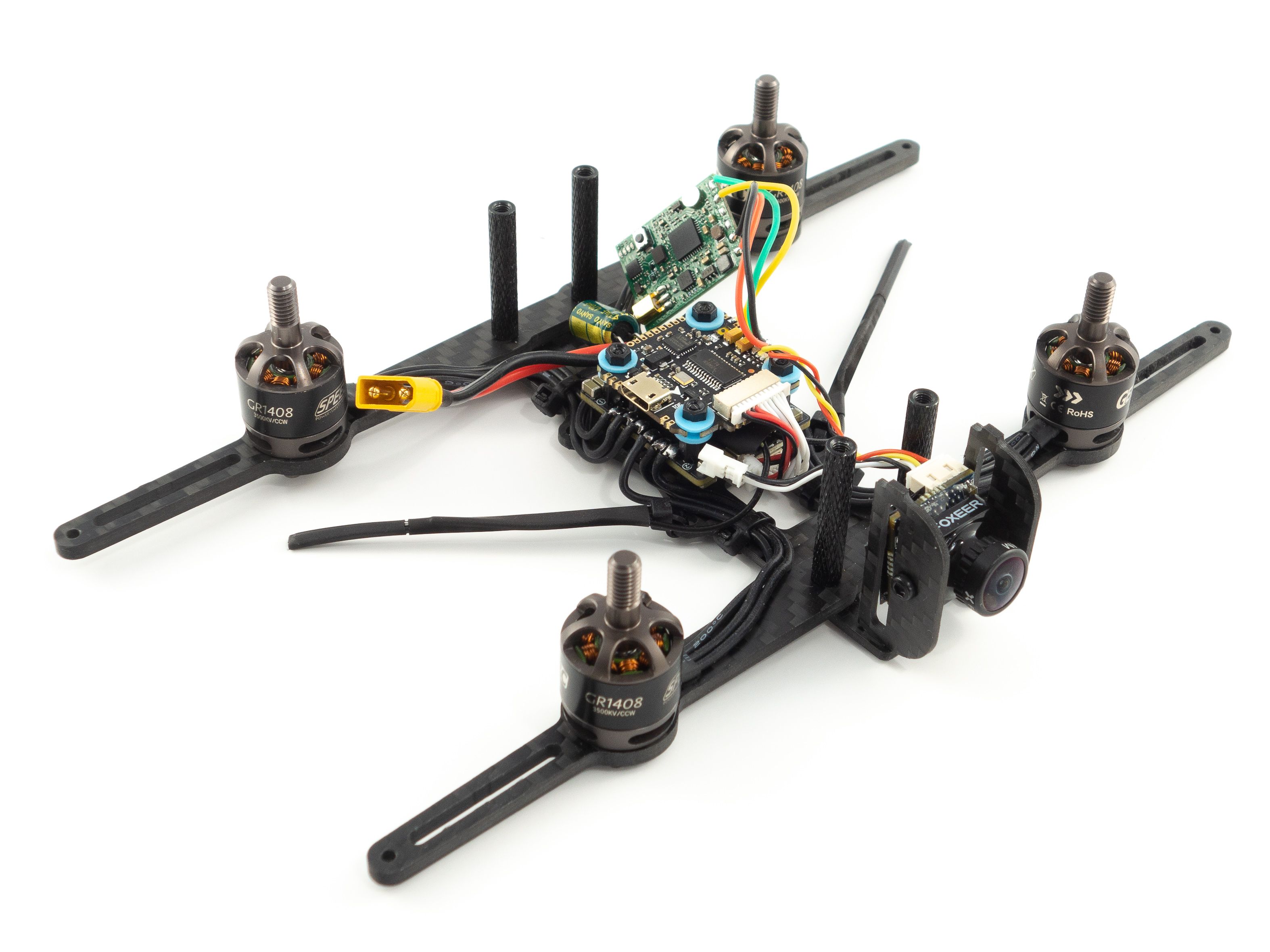
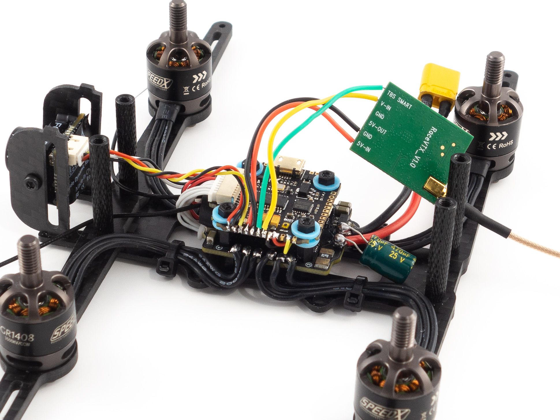
The flight controller doesn't come with instructions, nor are there labels on the pads, so it's crucial to reference the wiring diagram. For this build you'll need to use just about every pad on the left side of the board. Refer to the diagram below. These pads are really tiny, so don't apply too much solder and use plenty of flux. I found it easiest to solder the wires to the little grooves on the sides of the pads.
Binding the ReceiverNow that you've got power you can add the receiver and bind it. I used the FrSky XM+, but you'll need to choose a receiver that matches your radio.
- Solder 3 wires to the 5v, GND and SBUS pads on the receiver.
- I borrowed some wire from the camera. It's got enough to spare.
- Solder these wires to the 5v, GND and SBUS pads on the flight controller.
- Add your flight controller to the stack and re-connect it to the 4-in-1 ESC. Don't secure it with the nuts just yet.
- Bind your receiver
- Be sure to double check that you don't have continuity between your main battery leads and use a smoke stopper if you have one.
- Hold the bind button on the receiver while you plug the main battery in. (It's helpful to clamp this button down with tweezers to free your hand)
- Put your radio into bind mode and make sure you're bound.
- Now that you're bound you can add some shrink tube to your receiver and tuck it under the flight controller. Now secure it with the nylon nuts.
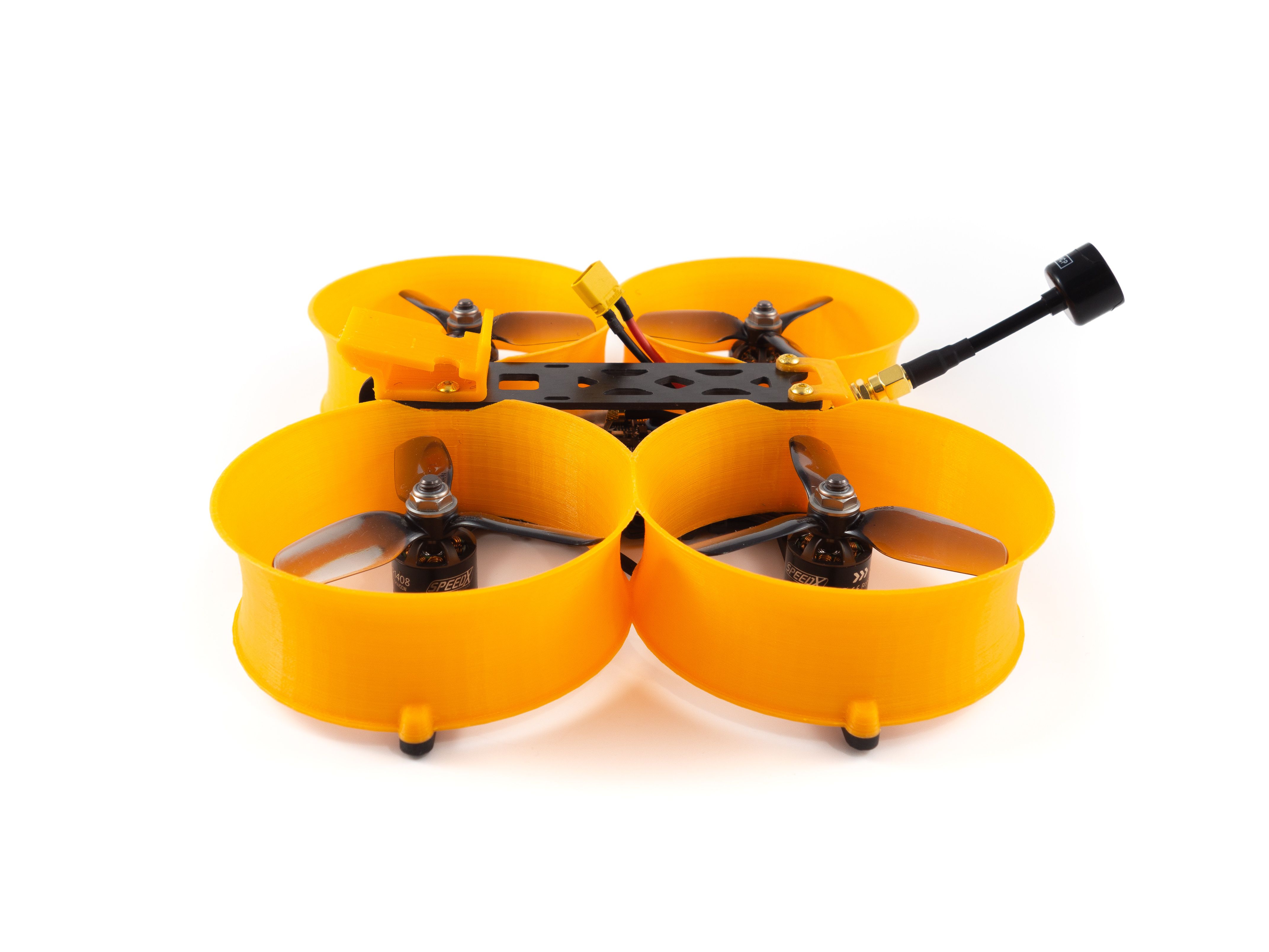
I had a hard time finding a place to mount the antennas. The arms are parallel to each other. Ideally we want the antennas to be at a 90 degree angle from one another, so I found a nice solution. The 30.5mm stack mount holes are perfect for a couple small zip ties. Just tighten them at a 45 degree angle toward the rear of the quad and you're all set! Secure the antennas to the zip ties with shrink tube.
CameraNext we can add the camera. First you'll want to screw the side plates to the camera and mount it onto the frame to measure the wire. Remove the purple wire and connect the wire harness to the back of the camera. Cut the wire giving yourself a little slack to adjust the camera angle. Refer to the wiring diagram for wire placement. You'll use the first three pads.
Video TransmitterNow for the VTX! De-solder the 5v out and GND wires from the board because we won't be using those. Give yourself enough slack to mount the VTX just behind the camera on the top plate. You'll want the antenna to point toward the rear of the quad. Again, refer to the wiring diagram to solder the wires to the flight controller. These will be the 4 remaining pads between the receiver and camera wires.
Camera ConfigurationNow that you've wired the camera and VTX you can adjust your camera settings. Plug in your quad and check that the video feed is functioning. Then, using the included joystick you can plug into the wired connector behind the camera. Mainly all you want to do is disable the camera OSD. We'll be using the OSD provided by the flight controller instead. Press and hold the up button to access the OSD menu. Disable each option and save.
Finishing UpOnce you've added the ducts it'll be difficult to reach the USB port, so I recommend a USB extension to avoid removing the ducts later on. If you don't have one you should skip ahead to the Betaflight Configuration section below and configure your quad before the final assembly. You may also want to put the props on before adding the ducts. The motors can be tricky to grip with the ducts in place.
- To finish up slide the ducts over the standoffs being careful not to squish the motor wires. You may need to adjust the wires to get a good fit.
- Make sure the ducts are right-side up so you can screw them onto the tips of the arms.
- Remove nuts and washers from the SMA pigtail and fit it through the TPU antenna mount. Put them back to secure it to the mount.
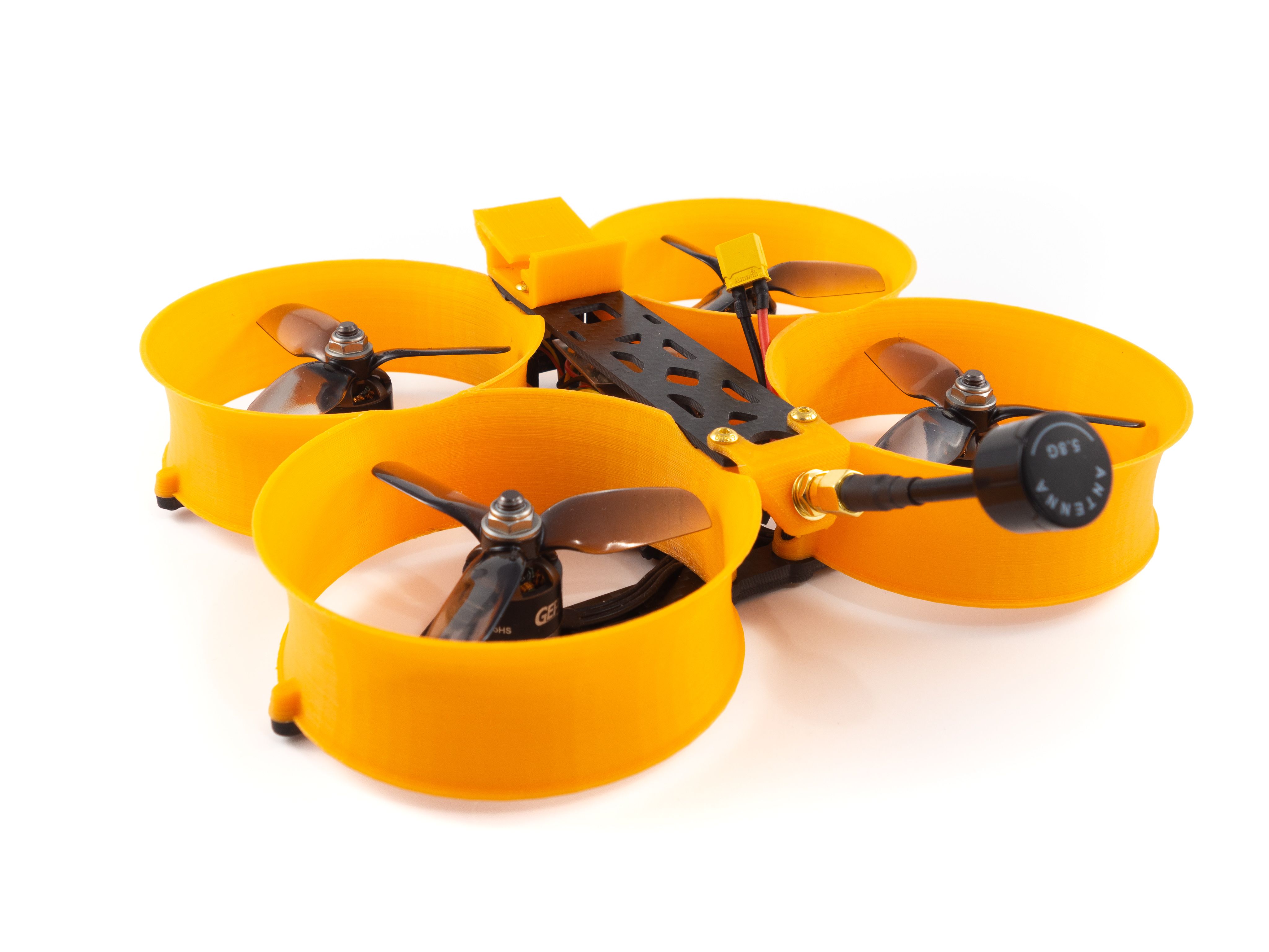
- I recommend getting some very wide shrink tube (~26mm) to cover the VTX. That way you don't need to tape it to the frame and it can float above the flight controller. That'll give you more flexibility with your battery strap.
- Screw the top plate into place with the TPU components for mounting the antenna and camera.
- Screw your SMA antenna onto the pigtail.
- Add a battery pad to the top to prevent battery ejections and slide a battery strap under the top plate.
If you don't already have them, you'll need to download Betaflight Configurator [Download] and the BLHeli Configurator [Download].
- First go to the Firmware Flasher and choose "FURYF4OSD" as well as the latest stable release of Betaflight.
- Click "Load Firmware [Online]" and then "Flash Firmware" to update your flight controller. Once complete, click "Connect"
- On the Ports tab
- On UART1 click Serial RX for your receiver.
- Set the UART3 Peripherals to "VTX (SmartAudio)".
- Click Save and Reboot
- On the Configuration tab
- Under ESC/Motor Features select DSHOT600
- Under System configuration set PID loop frequency to 8 kHz.
- Under Receiver choose your receiver mode. For the XM+ choose "Serial-based receiver" and "SBUS"
- Under Arming set the Max arm angle to 180 (Only if you keep the accelerometer turned on)
- Under Other Features enable: Airmode, OSD, Anti Gravity and Dynamic Filter
- Under DSHOT Beacon Configuration enable the beacon
- Go to Power & Battery and choose Onboard ADC for the Current Meter Source
- Click Save and Reboot
To complete the remaining steps you'll need to apply lipo power to your build:
- On the Receiver tab ensure your pitch, roll, throttle and yaw are being applied correctly. Adjust your transmitter and Channel Map as needed.
- On the Modes tab
- Assign an Aux switch to arm and disarm your quad.
- Assign another Aux switch to enable Horizon or Angle mode if you need them.
- Assign the Beeper and "Flip over after crash" to a 3rd and/or 4th switch. I like to assign them both to a single 3 point toggle switch.
- On the Motors tab enable the motor test and apply a small amount power to check the rotation of each motor. Take note of any that need to be reversed.
- Disconnect from the Betaflight Configurator and open BLHeli Configurator
- Connect and Read Settings
- Flash all ESCs to the latest firmware available.
- Reverse the motor direction of any motors that need it. (The numbers correspond to the same numbers in Betaflight)
- Save and reconnect to Betaflight Configurator to test the motor direction.
- On the OSD tab
- Check all of the features you want and arrange your OSD as desired.
And that's it! The default Failsafe settings are generally fine, but make sure they work by arming your quad, applying a small amount of throttle and turning off your transmitter. It should shut down after a short moment.
ChallengesThe biggest challenge was soldering the tiny pads. I found it worked best to rest my wrist on a flat surface to steady my hand. The more steady you are the better. You just want to avoid bumping adjacent solders causing them to flow together. Other than that I spent a fair bit of time finding a place to mount the receiver antennas. It wasn't the most difficult build, but it did require some patience.
In terms of motor heat, between the HQProps and the Gemfans I found the Gemfans to run cooler. The motors do tend to get hot on these ducted builds, but with very low d-term values on the Gemfans they're coming back reasonably warm, but not burning hot.
Source: RotorBuilds.comGalerija